


Friday 14th March 2025
8.0 ForewordGirder trolleys are generally used as a means of moving a load suspended on a structural section in conjunction with a hand or power-operated lifting appliance. They are commonly used on runways, jib cranes, mobile supporting structures, and overhead travelling cranes.
This section does not provide specific guidance for power-operated trolleys, as they are usually considered part of the combined hoist system. Refer to Section 1 Appendix 6 and Section 6 for details. However, the general principles discussed here may still apply to their selection and use.
There are few standards specific to girder trolleys; many are built to manufacturer specifications. Users should ensure compatibility with the structures they will be mounted on. Also see:
Section 3: Safe Use of Hand Operated Chain Hoists
Section 6: Safe Use of Power Operated Hoists
8.1 Scope
8.1.1 This section refers exclusively to manually operated girder trolleys. Power-operated trolleys (electrical, pneumatic, hydraulic) are considered part of the lifting appliance they support.
8.1.2 Built-in pattern chain hoists are acknowledged but not discussed in detail here. See Section 3 for hand chain hoists and Section 6 for powered hoists.
8.1.3 Some trolleys are designed for specialized tracks, not standard steel section flanges. These are not included in this guidance. Competent manufacturers will provide the necessary design and use information.
8.1.4 Trolleys used in people-carrying applications are also excluded. Always consult the manufacturer for such uses.
8.2 Definitions
8.2.1 Runway A runway is any structural section, provided it is suitable for use as a runway beam, i.e. designed for the appropriate load cases and fitted with appropriate safety components such as end stops, and is suitably supported. (See section 1, appendix 1.4)
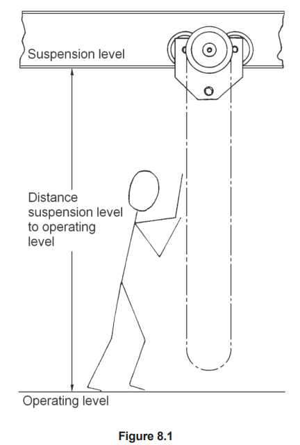
8.2.2 Suspension Level The suspension level is the level of the surface on which the trolley runs.
8.2.3 Operating Level The operating level is the level on which the operative stands.
8.2.1 Runway A runway is any structural section, provided it is suitable for use as a runway beam, i.e. designed for the appropriate load cases and fitted with appropriate safety components such as end stops, and is suitably supported. (See section 1, appendix 1.4)
8.2.2 Suspension Level The suspension level is the level of the surface on which the trolley runs.
8.2.3 Operating Level The operating level is the level on which the operative stands.
8.2.4 Load Bar The load bar is that part of the trolley to which the suspended load or lifting appliance is attached. The exact form of the load bar depends on the design of the trolley and may include a hook, eyebolt or similar suspension point.
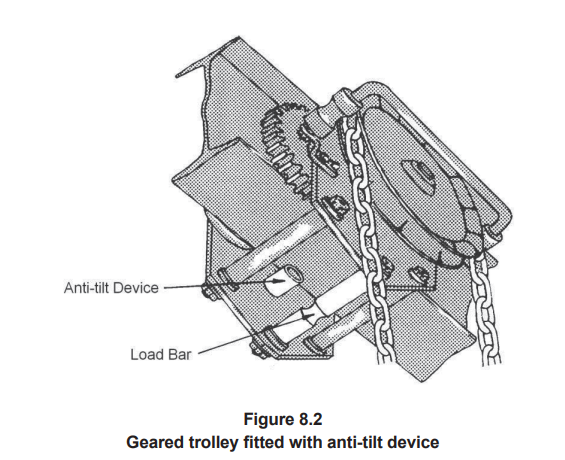
8.2.5 Anti-Tilt Device An anti-tilt device is an adjustable roller or similar device fitted to a gear operated trolley. This operates against the underside of the bottom flange of the runway or other suitable part of the beam section, to prevent the trolley tilting when the hand chain is operated. Certain manufacturers also fit similar devices to hand pushed trolleys.
8.3 Types of Girder Trolley
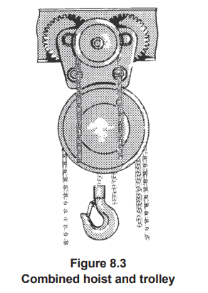
8.3.1 Suspension Arrangements The plain trolley is fitted with a device in the form of a load bar, hook, or eye from which a lifting appliance may be suspended by its head fitting. Other trolleys are designed to have the lifting appliance permanently attached. These are known as ‘combined’ or ‘built-in’ trolleys.
8.3.1 Suspension Arrangements The plain trolley is fitted with a device in the form of a load bar, hook, or eye from which a lifting appliance may be suspended by its head fitting. Other trolleys are designed to have the lifting appliance permanently attached. These are known as ‘combined’ or ‘built-in’ trolleys.
8.3.2 Operation Trolleys are available with a choice of hand push or gear operation. A hand pushed trolley is usually moved by pushing the suspended load. It is also possible to move the trolley using a winch or other pulling machine. A geared trolley is provided with geared driving wheels, which are rotated by pulling downwards on a hand chain that drives an intermediate gear.
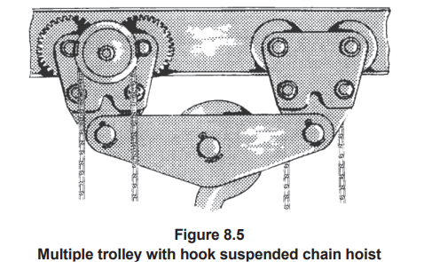
8.3.3 Wheel Arrangement The most common types of trolley have a four-wheel arrangement (two pairs). Two-wheel trolleys are available for certain applications and are usually associated with lighter loads. In some cases, two or more two-wheel or four-wheel trolleys may be connected by a purpose-made load bar to increase the rated capacity.
8.3.4 Types of Wheel Most modern trolleys are fitted with wheels having a tread profile suitable to run on any standard constructional section flange or for a specific profiled track section. Older trolleys and those for certain applications may have wheels with tread profiles to suit specific flange sections, such as tapered flange RSJ. Common trolleys may have plain bushed bearings, while anti-friction bearings are available for heavier loads and special applications.
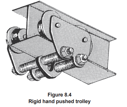
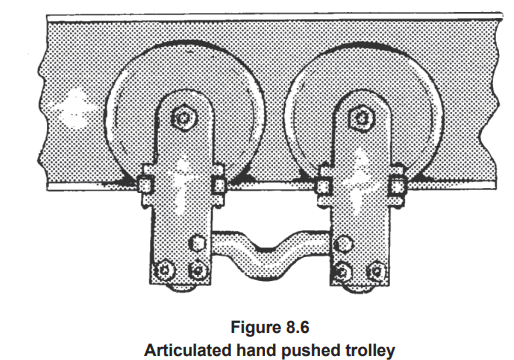
8.3.5 Rigid or Articulated Rigid trolleys have wheels arranged on fixed side plates and are best suited for straight runway beams or those with a generous radius. Articulated trolleys have four or more wheels and are designed so each set of wheels can pivot relative to the others in plan.
8.3.6 Beam Compatibility Trolleys are available to suit a wide range of beam widths. Most modern types are adjustable to suit a limited range and must be correctly set for the beam onto which they are mounted. Older types may be suitable for only one specific beam width.
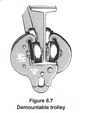
8.3.7 Demountable Trolley Combined hoist and trolley appliances are usually used in permanent applications. Plain trolleys are often left in place, even when the lifting appliance is removed. Rigid trolleys are available in demountable designs for temporary use where the trolley needs to be frequently moved from one runway beam to another.
8.4 Principles for the Selection of Girder Trolleys
8.4.1 SWL The rated capacity of the trolley selected should allow for any additional weight other than the load which is to be suspended from it. In most cases, manufacturers of trolleys take into account the weight of a hoist of their own specification in assessing the rated capacity. If a heavier lifting appliance or one of different duty than that normally specified is to be used, this must be taken into account when establishing the SWL. It is important that the type of lifting appliance to be used (i.e. hand or power operated) is considered.
If a trolley intended for hand operated appliances is to be used with a power operated appliance, then a de-rating of at least 15% should be made. No allowance is necessary if a hand operated appliance is used with a trolley intended for power operated appliances. Account should also be taken of the additional weight of the power operated appliance. In assessing the total load to be lifted, the weight of any lifting equipment or accessories, which will be suspended from the lifting appliance, must also be added to the total load.
8.4.2 Separate Trolley and Hoist or Combined Hoist The frequency of use of a hoist attached to a trolley will generally determine whether or not a combined hoist and trolley is to be used. Many users find it convenient to leave only the trolley on the runway and use a hook suspended hoist when a lift is required. A combined hoist and trolley will usually take up less headroom than a separate hoist and trolley of the same working load limit and duty.
8.4.3 Hand Pushed or Geared Trolley The particular application will to some degree determine the choice between hand pushed operation or geared operation. Hand gear operated trolleys are generally used for heavier loads and where a greater degree of control is required over the movement of the load. They are also used if the height of lift or distance between the operations level and the suspension level is such that it would be difficult to move the load using a hand pushed trolley.
8.4.4 Wheel Bearings Wheels fitted with anti-friction bearings greatly reduce the effort required to move the load and these are recommended for heavier loads and frequent operation.
8.4.5 Curved Runway Beams Difficulty may be experienced in negotiating small radius bends (typically less than 2 or 3 metres). Manufacturers state recommendations on the minimum radius bend their equipment can negotiate. Articulated trolleys will negotiate smaller radii than rigid trolleys with the same wheel centres. A two wheel trolley will negotiate any radius of curve that can be practically manufactured on a runway beam provided the wheel flanges do not foul the beam flange on the inside of the curve.
8.4.6 Beam Width Adjustment Adjustable width trolleys are available to fit runway beam flanges within limited ranges. These are useful if the trolley is occasionally to be moved from one beam to another, but extreme caution must be observed to ensure that it is properly fitted and adjusted to the correct width.
8.4.7 Temporary Applications Trolleys which are designed to be readily demountable are available. These are suitable for temporary use when the trolley is to be moved frequently from one runway beam to another. As with the adjustable width trolleys, care must be taken to ensure that this type of trolley is properly fitted and adjusted. Specific installation instructions should be obtained from the manufacturer.
8.4.8 Wheel Tread Profile Trolleys with wheel tread profiles designed to run on non-standard or old constructional sections may not be suitable for use on standard beam sections and vice-versa. Most modern trolleys have wheel profiles to suit standard sections and advice should be sought from the manufacturer or supplier on this point.
8.4.9 Documentation When selecting a trolley, ensure that it is covered by the necessary documentation required by legislation. If this is not on record, refer the trolley to a Competent Person for thorough examination.
8.4.10 Stops The trolley buffer stops must be of adequate shape, size and position to engage with the runway end stops.
8.5 Information Which Should Be Exchanged Between the User and the Designer or Supplier
As girder trolleys are frequently used for miscellaneous lifting applications, precise details of the load to be carried are not always available. In these cases, only a general specification can be given. This specification should include the following:
Example specification:
As girder trolleys are frequently used for miscellaneous lifting applications, precise details of the load to be carried are not always available. In these cases, only a general specification can be given. This specification should include the following:
- Type of trolley required.
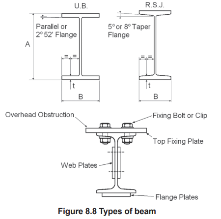
- Details of the runway beam section to which the trolley is to be fitted. These details must fully identify the section or, in the case of a fabricated beam, include the various elements from which it is made. Also include details of fixing bolts, clips, splices, etc., to ensure they won’t interfere with the load bar, trolley wheels, or anti-tilt device where fitted.
- Details of the supporting structure of the runway, including clearances to nearby structures or equipment, to ensure no external obstruction.
- The total maximum weight to be lifted.
- The type (manual or powered) and class of use of the lifting appliance to be used with the trolley.
- Details of the load bar or suspension point of the trolley and how the lifting appliance(s) will be attached.
- For geared trolleys: suspension and operating levels so the correct chain length can be determined.
- The minimum curve radius, if applicable, for the runway.
- Environmental considerations such as extreme temperatures or corrosive atmospheres.
- Rated capacity: 250kg
- Gear operated
- Four plain bearing wheels
- Rigid trolley
- 150mm flange width (parallel flange)
- Suitable for use with hook-suspended hand chain hoist
8.6 Legal Requirements
See Section 1, Subsection 1.3 of this code.
8.6.1 Examination and Documentation
Trolleys are classified as part of the lifting appliance they support. Unless a written scheme of examination (see LEEA 032) is in place, they must undergo thorough examination at intervals not exceeding 12 months. Examination reports must be retained and cross-referenced with the trolley’s history for inspection by a Competent Person or local enforcing authority.
A thorough examination may also be necessary before first use (see Section 8.7) depending on the application.
8.6.2 Post-Repair Verification
After any repair, a Competent Person must re-verify the trolley. The report must be kept and cross-referenced in the equipment’s history file.
📌 Note:
Although not legally required, new trolleys are typically issued with a manufacturer’s proof load test certificate. This should be retained and made available during inspections.
8.7 Installation and Commissioning
8.7.1 Erection of the Equipment
The installation of the trolley must follow the manufacturer’s instructions and also align with the commissioning procedure for the lifting appliance it supports. Key considerations during erection include:
- Pre-installation check – Ensure no damage occurred during storage.
- Structural adequacy – Verify that the supporting structure is capable of bearing the combined load, which includes the trolley, hoist, slings, shackles, and dynamic load allowance (10% for manual, 25% for powered appliances). If attached to a building, seek written approval from a structural engineer or architect. (See Section 1, Appendix 1.4)
- Correct selection – Confirm the trolley is of a suitable type and capacity for the application.
- Beam compatibility – Ensure the trolley fits the specific runway beam.
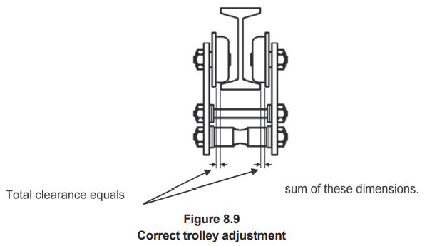
- Width adjustment – For adjustable trolleys, verify it is correctly set for the beam width, centered on the flange, and with total side clearances (usually 3mm–4mm) per manufacturer’s guidelines.
- Reassembly check – If disassembled for fitting, ensure the trolley is correctly reassembled.
- Runway end stops – If removed during installation, reattach them securely. Stops should prevent the trolley from passing and should not engage the wheel flanges.
- Anti-tilt device – Ensure it is properly adjusted and not obstructed beneath the flange.
- Tightening – All nuts and bolts must be tightened as per manufacturer’s specifications.
- Electrical safety – For powered hoists, do not use the trolley or runway as an earth return. Use a separate earth conductor and install in accordance with electrical safety regulations.
The level of inspection required depends on trolley type and installation conditions.
- Demountable trolleys (often used for maintenance) may only need visual inspection by a qualified person before use to confirm proper fitting and adjustment.
- Permanent trolleys (which may involve disassembly and reassembly) should undergo a thorough examination by a Competent Person. (See Section 8.6)
8.8 Marking, Storage and Handling
8.8.1 Marking
Each trolley must be permanently and legibly marked with the following:
8.8.2 Storage and Handling
8.8.1 Marking
Each trolley must be permanently and legibly marked with the following:
- Identification mark – If the manufacturer hasn’t provided one, the user must add one for linking to inspection reports.
- SWL or rated capacity
- Type of lifting appliance – Indicate if suitable for hand or power operated appliances.
- Beam compatibility – Indicate the designed flange width or adjustable range.
- Year of manufacture
- Manufacturer’s name and address
8.8.2 Storage and Handling
- Storage: Trolleys not permanently installed should be stored in a secure, dry area as outlined in Section 1.
- Disassembled trolleys – Check that all parts are correct, properly matched, and reassembled before reuse.
- Geared trolleys – Store hand chains carefully to prevent damage.
- In-situ trolleys – Should be parked safely near the runway end stop to avoid exposure to operations or potential collisions.
- Outdoor storage – Use weather protection (e.g., tarps or covers).
- Handling – Do not drop or throw down trolleys. Reassemble all components properly after any dismantling.
8.9.1 Pre-Use Inspection
In addition to statutory thorough examinations, all trolleys should be visually inspected by a suitably qualified and experienced person:
- For regularly used trolleys: inspect at the start of each shift or working day.
- For infrequently used trolleys: inspect before use on each day of use.
- Inspection date
- Confirmation that it passed
- Inspector’s name and signature
Defects requiring removal from service include:
Interim inspections may be required depending on usage, wear risk, and environment. They should be based on a risk assessment considering:
- Worn wheel treads, damaged flanges, or bearings
- Loose wheels or axle pins
- Bent or distorted side plates or load bar
- Wear on load-bearing parts
- Cracked or poor welds
- Incorrect or substituted parts
- Damaged or corroded hand chain (especially inner bearing surfaces)
- Illegible markings (SWL, ID, etc.)
8.9.2 Additional Inspection for In-Situ Trolleys
Additional checks should confirm:
Additional checks should confirm:
- Correct trolley size for the runway beam
- Proper adjustment – Trolley should be centered and maintain the correct side clearance (usually 3–4mm).
- Anti-tilt device – Confirm correct setting and freedom of movement
- Correct hoist – Ensure it is properly fitted and suitable
8.9.3 Interim Inspection
Interim inspections may be required depending on usage, wear risk, and environment. They should be based on a risk assessment considering:
- Manufacturer’s guidance
- Environmental conditions
- Frequency of use
- Type of loads
8.9.4 Maintenance
Follow manufacturer’s instructions and any site-specific requirements.
Minimum attention points:
Routine overload testing is not recommended unless:
Disadvantages of unnecessary overload testing:
Alongside the manufacturer’s instructions, follow these guidelines:
8.11 Training
In addition to the general training requirements in Section 1, Subsection 1.9:
Follow manufacturer’s instructions and any site-specific requirements.
Minimum attention points:
- Clean and lubricate all moving parts. Avoid contaminating wheels and beam flanges.
- Remove debris or fluids from wheels and beams that may cause slippage.
- If beam shows distortion or wear, or if end stops are missing/ineffective, remove from service and consult a Competent Person.
8.9.5 Thorough Examination
A thorough examination by a Competent Person is required at 12-month maximum intervals, unless governed by a written scheme of examination (per LEEA 032).
- Use a compliant report format and retain it in historical records
- Report any defects and investigate root causes (e.g., operator error, poor training)
- Remedy issues and document actions before returning trolley to service
- Non-destructive testing (NDT)
- Functional or electrical safety testing
- Overload testing (only when deemed necessary)
Routine overload testing is not recommended unless:
- Required by national legislation or manufacturer
- Following significant modification or repair
Disadvantages of unnecessary overload testing:
- Can cause fatigue or hidden damage
- May not detect cracks or flaws
- Risk of expensive damage if failure occurs during test
8.10 Safe Use of Girder Trolleys
Alongside the manufacturer’s instructions, follow these guidelines:
- Do not exceed SWL – Never suspend a load beyond the marked capacity.
- Avoid shock loading – Prevent sudden vertical or horizontal loads (e.g. from jerking or collisions).
- When using multiple trolleys, ensure none is overloaded.
- Temperature exposure – Avoid storing or using trolleys in extreme conditions.
- Never allow personnel under a suspended load.
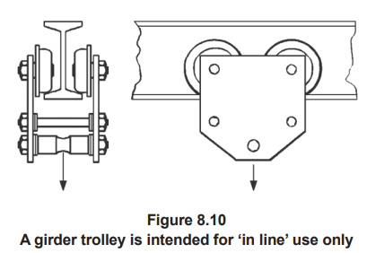
- Ensure ‘in-line’ use – The vertical load must align perpendicular to the runway flange.
- Loads applied at angles may shift and create uneven stress.
- Avoid any sideways pulling; it may cause derailment. Use a movable runway if the load is not under the beam.
8.11 Training
In addition to the general training requirements in Section 1, Subsection 1.9:
- Personnel erecting trolleys must be trained in correct assembly and fitting
- Operatives must be aware of which parts of a structure are suitable to act as runway beams and their load capabilities
- Always follow the manufacturer’s instructions for installation and use.